Product case study · Central controller · Since 2002
M-Controller II
A universal digital-and-analog control platform for centralized gas monitoring — interfacing up to 40 sensing points, driving up to 99 relays through distributed expansion, and integrating into building automation over Modbus and BACnet.
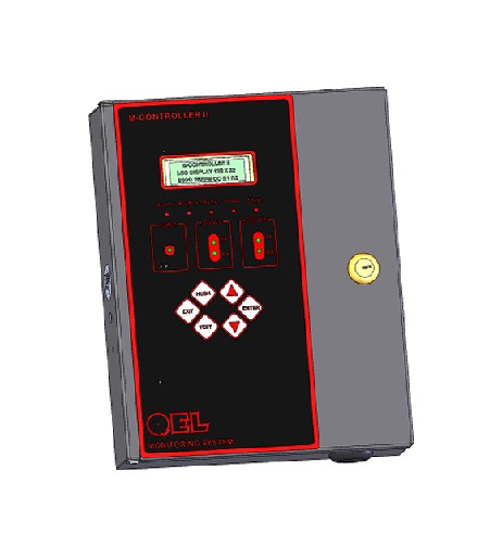
Overview
A control centre for distributed gas detection.
The M-Controller platform brings remote gas transmitters, analog sensors, alarms and control outputs into one programmable system. A single controller can supervise a mechanical room or scale up to a parking structure, refrigeration plant or industrial facility.
It displays gas readings, evaluates alarm conditions, activates local or remote relays, drives horn and strobe outputs, and makes system information available to external automation platforms. M-Controller II continues a platform first released in 2002 — with the installed base, expansion modules and software ecosystem that come with two decades of field service.
Engineering challenges
Four problems that shaped the design.
1 · Scale without a redesign
One controller had to serve a small mechanical room and a 40-point facility with 99 relays. That ruled out fixed I/O — capacity had to grow through distributed modules on a field bus.
2 · Mixed digital and analog sensing
Sites combine smart digital transmitters with legacy 4–20 mA devices. Both had to feed one consistent alarm engine, with the same setpoint, voting and relay logic regardless of source.
3 · Building-automation integration
Gas systems must report into BMS platforms that standardise on Modbus or BACnet — without the safety logic depending on a network that may be down.
4 · A twenty-year installed base
Units sold in the 2000s still run today. Every enhancement had to preserve compatibility with fielded sensors, relay modules and wiring.
System architecture
A supervisory core with distributed I/O.
Capacity lives in modules on an RS-485 network rather than in the controller chassis, so a system is sized by adding hardware — not by replacing the controller.
Sensing layer
Up to 32 digital transmitter/sensors on RS-485 multidrop, plus 8 analog 4–20 mA channels for legacy and third-party devices.
Control core
Reading acquisition, alarm evaluation, voting, and output logic — running independently of any supervisory network.
Output layer
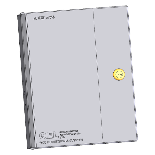
Onboard relays plus M-Relay expansion modules (up to 11) for a maximum of 99 relays, isolated 4–20 mA retransmission, buzzer, horn and strobe.
Supervisory layer
Modbus for BMS integration, BACnet/IP through the BAC-Box converter, and M-View / M-Net for configuration, monitoring and logging.
Electronics
Mixed-signal acquisition and protected outputs.
The hardware combines precision analog input conditioning, an isolated RS-485 field-bus interface, relay drive and annunciation outputs, and the power architecture to feed remote sensors over long cable runs in electrically noisy plant environments.
Firmware
Real-time supervision and deterministic alarms.
Acquisition & alarm engine
Polling of digital sensors and analog channels, setpoint evaluation, voting across multiple sensors, latching and hush behaviour.
Output control
Relay assignment and mapping across onboard and remote modules, annunciation, and isolated analog retransmission.
Communications
RS-485 sensor networking plus Modbus for supervisory integration, coordinated with remote relay and display modules.
Configuration & diagnostics
On-device menus, stored configuration, calibration state, fault detection and service information for field troubleshooting.
Mechanical design
Panel-oriented, field-serviceable.
The enclosure, display and keypad, terminal layout and cable access were developed alongside the electronics — prioritising accessible wiring terminals, clear front-panel indication, and straightforward mounting in mechanical rooms and equipment areas.
Software ecosystem
The controller is only half the product.
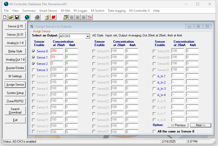
M-View — configuration & monitoring
Windows application for system configuration, live monitoring, relay mapping and service — developed alongside the controller from 2003.
M-Net & M-Logger
Networking and data logging for distributed systems, extending the platform toward Ethernet and remote monitoring.
Expansion modules
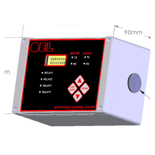
M-Relay, QRP remote display, M-Annunciator and M-Switch — each designed as part of the same system architecture.
BAC-Box converter
Presents the controller's gas system as individual BACnet objects on a BACnet/IP network.
Applications
Designed for real-world safety systems.
Gallery
Controller, software and expansion.
Development timeline
A platform, not a product release.
Lessons learned
What two decades of this platform taught.
Put capacity on the bus
Moving I/O growth into modules on RS-485 meant one controller design could serve installations of vastly different size — and could grow after commissioning.
Keep safety off the network
Alarm evaluation and relay control run locally. Supervisory communications add visibility without becoming a dependency for the safety function.
Ship the software with the hardware
M-View was not an accessory. Configuration, monitoring and service tooling determined how the system was actually deployed and maintained.
Compatibility is a feature
With units still running from the 2000s, backward compatibility with fielded sensors and modules is worth more to customers than any single new capability.
Notes on this case study
This page describes publicly documented product capabilities and my own engineering contribution at a high level, rather than confidential design detail. Product names, trademarks, documents and commercial specifications belong to their respective owners.
View the public QEL controller page ↗